-- Veröffentlicht durch dergeert am 13:10 am 28. Nov. 2004
sorry, i cant't get involved too much with all the vid lines etc, this is getting confusing :blubb: however, it seems you have got the right idea now.
if you have chosen the right pin, probably the varnish is no good.
here's a little mod i did yesterday to my mobo, because i got sick of cutting the bridges of all new cpu i want to undervolt:

i carefully enlarged one pinhole in my socket. when this pin is deactivated you get a voltage drop of -0,4V for any socket a cpu that operates at >=1,5V standard.
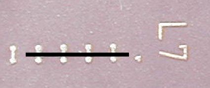
after this i was ready to isolate the pin with a delicate cable sleeve:

damn i isolated the wrong one...
here i chose the right pin and cut the isolation to length:

the so-prepared cpu fits into the modded socket and operates at vcore-0,4V if vcore was 1,5V (or more) initially.
when removing the cpu the tiny isolation bit sometimes likes to stay in the socket, so remove it with a needle without pushing it in. also make sure pushing it up all the way on the pin in the first place.
i think this should help as it is an almost non-destructive method (especially cpu-wise) :thumb:
(Geändert von dergeert um 17:18 am Nov. 28, 2004)
-- Veröffentlicht durch innuendo am 22:42 am 27. Nov. 2004
yes, you are right. you do not need to isolate all pins however, because some probably are not connected in the L7-bridge, so they are "isolated" already. also you only need single wire bridges, you do not need to put them all in as shown in the pinmod guide, because some are already connected in L7. what you need to do really is take a good look at the pinmod guide, the painting guide and maybe the schematics and see how they all work together. what is your current vcore/L7 configuration? |
Okai.. let's go on with my mod... :
I tried to go from 1,750 to 1,450volts ! After my experiments, the voltage is at 1,850 ... it dosen't work ! argl !
I'll explain you what I've done, and you'll tell me what's wrong.
The original setting for the L7 bridges are :
| | X | | ----> "|" stands for closed "X" for opened
vid4 3 2 1 0
I want to achieve this setting :
X | | | |
vid4 3 2 1 0
So... I only have to change the state of vid4 and vid2 (AM I WRONG?).... let's go.. !
This is what i've done :
First : Isolating vid4 pin on the cpu (by using varnish)
Second : Put a wire bridge beetween two socket holes : vid2 and vss.
When i realised that it dosen't worked, in unpluged the CPU and take the varnish to paint another layer on the vid4 pin ! But, it dosen't work : the result is exactly the same : my vcore is set to the maximum : 1,85volts (also a jump of +0,1volt)
What are my results saying ?
My current setting is 1,85volts, that is to say L7 = X X X X X
I conclude that the wire bridging of vid2 works well, but the isolated vid4 pin not !
Do I forget something ? Probably may I isolate the vid4 pin AND put another wire bridge somewhere... ? May I simply cut the vid4 pin ?
In my bios, the value displayed is exactly the same as before, but motherboard monitor or sisoftware Sandra says that the voltage is dropped to 1,89volts (1,85 in fact). This is bizarre..... (why is my BIOS reporting a bad value?)
Please tell me where are my errors... !
(One time, i'll do it ! I think i'm not far from the end)
(Geändert von innuendo um 22:50 am Nov. 27, 2004)
-- Veröffentlicht durch dergeert am 3:11 am 27. Nov. 2004
yes, you are right.
you do not need to isolate all pins however, because some probably are not connected in the L7-bridge, so they are "isolated" already.
also you only need single wire bridges, you do not need to put them all in as shown in the pinmod guide, because some are already connected in L7.
what you need to do really is take a good look at the pinmod guide, the painting guide and maybe the schematics and see how they all work together.
what is your current vcore/L7 configuration?
-- Veröffentlicht durch innuendo am 3:02 am 27. Nov. 2004
Okai... thanks ! I think i have understand all of the subject... (at least all of what i should do)
you will then know, which vid-pins to rip out in order to get to zero voltage (also you can rip out all five of them). then you can apply the pinmod with little wire-bridges to set your desired voltage. |
If I really understand what you said, this is what i have to do (for example) :
* First : cut all VID pins : from vid0 to vid4
* Second : use wire bridges to set my voltage : By pluging wires in the socket and each time beetween 2 holes : for example, beetween the place where "vid3 pin" should be and "vss".
Do you confirm ? (sorry for making you repeat, but consider i'm a real beginner in <"computer harware-modding">)
Again, Thanks a lot for helping me.
If you confirm, i will test it and come back to say if something works ! :thumb:
(Geändert von innuendo um 3:04 am Nov. 27, 2004)
-- Veröffentlicht durch dergeert am 2:50 am 27. Nov. 2004
i never tried the paint method but i thought of it already, too, and possibly it will work.
your voltage will drop if you paint vid pins that are connected on top of the cpu (L7 bridges), just as if you had cut that bridge.
possibly the voltage will be too low for your cpu to run, so you can raise it again step by step by using wire-bridges on other pins.
(Geändert von dergeert um 2:53 am Nov. 27, 2004)
-- Veröffentlicht durch innuendo am 2:40 am 27. Nov. 2004
Okai ! Thanks a lot !
I think the best way to do it is to do something from wich i can go back... (that i can undo).
The only "safe-mod" I know is to take some paint or nail varnish and paint the pin that i should cut, on the backside of the CPU (where all pins are)
Is it a good way ? :noidea:
So... we must resume :
"To undervolt my CPU, the only thing I have to do is to take some varnish a paint the pins that i want to set to 0 (or 1)"
No need of wire-bridging or anything else ?
(I recall you that my motherboard isn't able to change any voltage at all: nor with bios, nor with any other software...)
(Geändert von innuendo um 2:43 am Nov. 27, 2004)
-- Veröffentlicht durch dergeert am 0:59 am 27. Nov. 2004
you must cut something in order to lower the voltage, be it the bridges on top of the cpu, lines on the mobo or rip out pins.
just connecting pins will only result in higher voltage or no change at all.
-- Veröffentlicht durch innuendo am 19:18 am 26. Nov. 2004
First of all, thanks a lot for answering my message and trying to help me !
just check your default core voltage with a system monitoring tool (or maybe you already know), enter it in the pinmod guide and compare the resulting picture to the pinout in the datasheet. you will then know, which vid-pins to rip out in order to get to zero voltage (also you can rip out all five of them). then you can apply the pinmod with little wire-bridges to set your desired voltage. |
This is exactly what i've done, but it dosent work. To do it, i used a wire bridge beetween VID4 and VSS as you can see on the upper picture. If i correctly understand, this is the same as isolating the
VID4 pin.
Am I wrong ?
May I furthermore cut de VID lines on the motherboard or the voltage regulator or are the wire bridge(s) sufficient ?
(Geändert von innuendo um 19:26 am Nov. 26, 2004)
-- Veröffentlicht durch dergeert am 12:12 am 26. Nov. 2004
why don't you try breaking some pins as i suggested already?
or get a better cpu/board.
there's nothing else i could tell you, really :dontknow:
-- Veröffentlicht durch innuendo am 9:30 am 26. Nov. 2004
Can't anyone help me ? :noidea: :godlike:
Please ! Tell me anything...
I want to change the vcore for my processor !
-- Veröffentlicht durch innuendo am 23:33 am 6. Nov. 2004
up please ! :thumb:
-- Veröffentlicht durch innuendo am 14:40 am 16. Okt. 2004
Okai... let's go on again with my story...
I tried to do the pin mod by doing this : 
But it simply dosent work. I'm sure i've done it well.
I tried to combine this with and without L1 bridges closed, but it dosen't work !
May I close/open some other bridges ?
(it seems to be hard to find info about what i want to do..
Please help me, or i'm gonna be crazy :blubb:)
:lol:
-- Veröffentlicht durch dergeert am 13:50 am 5. Juli 2004
:thumb:
just check your default core voltage with a system monitoring tool (or maybe you already know), enter it in the pinmod guide and compare the resulting picture to the pinout in the datasheet.
you will then know, which vid-pins to rip out in order to get to zero voltage (also you can rip out all five of them).
then you can apply the pinmod with little wire-bridges to set your desired voltage.
-- Veröffentlicht durch innuendo am 13:40 am 5. Juli 2004
Best thanks to everyone !
I sorry ! I haven't tried a google search with "datasheet", but with "pinout schematic" and that's why i didn't find anything.
My english is poor...
Now i'll try to understand these schematics..
If anyone has some good advices, i'll listen to them !
Thanks !
-- Veröffentlicht durch dergeert am 13:31 am 5. Juli 2004
google-search, first link dude....
page 58 and following.
i would guess that voltage pins for thunderbird and thoroughbred/barton are the same, because the mainboard/socket is compatible...
please do some research yourself now, i'm not going to look into that datasheet...
-- Veröffentlicht durch innuendo am 12:20 am 5. Juli 2004
The points on at the bottom aren't connecten with each other. |
How do you know it ? Can you give me a link (url) to a schematic for the thunderbird ?
by the way this is not the only way to undervolt for you. check out the pinmod section of workshop and think about isolating or breaking single cpu-pins...or using them as second contact for burning... |
I wanted to do this, but there isn't any pinmod guide for the thunderbird...
Am I wrong ?
The only one I could find is here, and NOT for thunderbird.
https://www.ocinside.de/go_d.html?=html/workshop/pinmod/amd_pinmod_d.html
-- Veröffentlicht durch dergeert am 9:56 am 5. Juli 2004
Zitat von innuendo am 1:03 am Juli 5, 2004 I understant what you're thinking. But if the electrical schematic was like this, could it work ?  (The little black rectangles represents the micro-fuses) True OR false ? So... does anyone know the easyiest solution to do this ? I'm sure someone knows what is this contact on the right of the picture. Thanks for helping me ! (I don't want to continue drilling my processor because I think i'll destroy it, i don't have the good tools to do it) |
if the schematics are correct and if the fuses are significantly smaller in cross-section area than the other line, it could work.
by the way this is not the only way to undervolt for you.
check out the pinmod section of workshop and think about isolating or breaking single cpu-pins...or using them as second contact for burning...
but think, before you break!!!
each voltag-pinmod uses 2 pins, and you must only break one of them- the one connected to the bridge (get a pinout schematics of thunderbird!!)
also you could cut and alter the vid lines somewhere on your board on the way to the voltage regulator...
get a datasheet of the voltage regulator and see, which pins vid(0..4) are and alter them there.
good luck ;)
(Geändert von dergeert um 10:10 am Juli 5, 2004)
-- Veröffentlicht durch Jack the Ripper am 7:02 am 5. Juli 2004
It's impossible. The line will be cut anywhere. It could also be cut in the horizontally part of line. You cannot control the the point where it burns.
And your paintin is wrong. The points on at the bottom aren't connecten with each other.
-- Veröffentlicht durch innuendo am 3:50 am 5. Juli 2004
I want to cut those bridges to undervolt my processor.
On my motherboard (gigabyte ga7ZX-H (kt133a)), and with any bios it's impossible ! I tried with cpumsr too... but it's not possible !
The only way is to cut those bridges on the processor.
This schematic is not correct. It's only only a supposition.
I only want to know if it's possible to do it with this contact on the right of L7 bridges and I hope someone can help me
Please help ! :thumb:
-- Veröffentlicht durch darkpepe am 1:24 am 5. Juli 2004
I wonder why you would want to modify the L7 bridges...
Anyway, IF the schematic is right, you would just destroy the contact between the dot on the right and the last bridge, so it would be useless
-- Veröffentlicht durch innuendo am 1:03 am 5. Juli 2004
I understant what you're thinking.
But if the electrical schematic was like this, could it work ?
(The little black rectangles represents the micro-fuses)
True OR false ?
So... does anyone know the easyiest solution to do this ? I'm sure someone knows what is this contact on the right of the picture.
Thanks for helping me !
(I don't want to continue drilling my processor because I think i'll destroy it, i don't have the good tools to do it)
(Geändert von innuendo um 1:06 am Juli 5, 2004)
(Geändert von innuendo um 1:07 am Juli 5, 2004)
-- Veröffentlicht durch dergeert am 23:39 am 4. Juli 2004
vielleicht hat ja irgendwer noch nen tb rumfahren und kann mal nachmessen, ob der punkt rechts dasselbe potential hat wie die "weggebohrten"...?
even if those points you drilled away and the one on the right were electrically identical (which i don't know and the above german question is about), there would be a problem:
what if the connection burns where i put the yellow flash? then you couldn't continue burning the other bridges!

-- Veröffentlicht durch innuendo am 23:11 am 4. Juli 2004
No.. they aren't cut because it's not enough drilled... !
These picture are not photographies, i modified them with "photoshop". But my processor looks like on this picture
Sorry for the misunderstanding !
My hope is to use the contact that you can see on the right of this picture (labelled "number 2") Then I will apply a voltage between "number 1" and "number 2".
What is this contact on the right ? Can I use it to do what I want ?
-- Veröffentlicht durch Jack the Ripper am 22:19 am 4. Juli 2004
If these Pics aren't fake they are are allready cut. I cannot see a bridge anywhere. Burning them would not cause anything because they are alredy gone.
But I have one problem with your pictures. Why can't I see any traces of your drill:noidea:
Even if you drilled them too much you would see a very small point.
-- Veröffentlicht durch innuendo am 21:58 am 4. Juli 2004
I drilled the down ends of the bridges a few weeks ago, and now I can't see these ends anymore !!!
I drilled them too much !
.... !
This picture is not fake ! My processor looks like this because i drilled the bridges !!
Please make serious answer
-- Veröffentlicht durch darkpepe am 21:47 am 4. Juli 2004
Your pics are fakes, take an original pic of your cpu
-- Veröffentlicht durch innuendo am 19:28 am 3. Juli 2004
Even with a magnifying glass, I can't see them !
I tried to sand it to see those ends, but it dosen't seem to be enough !
(i can't see them)
My hope is to use the contact that you can see on the right of this picture (labelled "number 2") :

Then I will apply a voltage between "number 1" and "number 2".
What do you think about it ? Will it burn the brige ? (at the bottom of "number 1")
What is this contact on the right ? Can I use it to do what I want ?
(Geändert von innuendo um 19:29 am Juli 3, 2004)
-- Veröffentlicht durch dergeert am 19:04 am 3. Juli 2004
also try putting conductive paint into the holes and contact thereafter.
or drill the shit out of that bridges to get them severed ;)
-- Veröffentlicht durch darkpepe am 18:11 am 3. Juli 2004
If there were no ends the CPU would be already unlocked or dead. Use a magnifying glass
-- Veröffentlicht durch innuendo am 15:22 am 3. Juli 2004
I said :
"I couldn't do it because the down end of the bridge is no more.
(I drilled them a few weeks ago, and now I can't see them anymore !!!!)"
I drilled them too much !
-- Veröffentlicht durch dergeert am 15:13 am 3. Juli 2004
the upper picture looks fake ;)
no way to tell, how your cpu really looks like, this way...
i guess you could try contacting with a needle where the bridge's endpoint supposedly is, even if you cannot see it.
-- Veröffentlicht durch innuendo am 15:04 am 3. Juli 2004
Hi everybody !
Sorry for not speaking german. I prefer speaking English though I come from France. (this message was already posted in the "english" topic, but no answer giving a solution)
Okai... i want to cut somme bridges on my thunderbird wich is in ceramic. I tried 3 times witch different tools (dremel, cutter, knife).
I've heard about something wich consists in applying a voltage beetween both ends of a bridge, to "burn" the bridge.
Ahemmm..
If only it could be easy..
Yesterday I tried to cut the bridge by applying a voltage beetween both end of a bridge.
But I couldn't do it because the down end of the bridge is no more.
(I drilled them a few weeks ago, and now I can't see them anymore !!!!)
You will say, "man, you're stupid". For sure, i was a brute, but please try to help me, I still want to burn those bridges ! :thumb:
Is there still a way to burn those bridges with the "burning by shortcut" trick ?
Mine looks like this :

I want to achieve this configuration (to set the lowest voltage) :
Thanks a lot for trying to help me !
PCSILENCIEUX (FRANKREICH)